Category Archives: Uncategorized

Incubator build: Part 2 – hardware AND software issues

I had successfully (maybe with an asterisk or two) kept a plastic tub roughly at a stable temperature. On to plastic tub v2! This is getting into mid-2018, and I’m starting to have a rough sense of things but for the most part I don’t know anything. Still using an ESP8266 and still using the Arduino wrapper. By this point, my Arduino program is getting pretty unwieldy, but it’s still less than 1000 lines. I had no idea how Arduino programs generally look, so it was pretty stream-of-consciousness with plenty of direction changes.

The original plastic tub had been scrapped (something about a giant hole melted in the side?), but luckily I had another. It was identical, but I’d learned my lesson. Ensuring the heater doesn’t burn anything down is priority number one. In the longer term, it was clear an incandescent light bulb wasn’t going to be the best heater for a number of reasons:

  • they get too hot (over 100°C easily)
  • they’re a weird shape, as heat is a byproduct and not the main use
  • they’re just not easily available anymore (that’s weird to say…)
  • they put off a ton of light, which doesn’t necessarily have an incubator-related downside, but it dissuades me from looking at the thing

I ordered a bunch of different styles of heaters, but they wouldn’t be showing up for a long time (almost everything I get is the cheapest version of itself and comes from China in 1 – 2 months). While a light bulb wasn’t ultimately going to be the goal, it’s what I had available to me. To make it safer I picked up one of these from the local home improvement store:

light-bulb-fixture

This was dramatically safer than my old light bulb holder, as by its very nature things are less likely to be close to it. I still just rested it on the bottom of the tub, but now it could be centered to maximize the distance from the sides.

When things go pear shaped – software side

Note that at this point while the project is keeping a relatively “fixed” heat, that’s pretty secondary. So much other stuff is going wrong that the fact it’s intended to be an incubator is virtually irrelevant. At this stage, I ran into two significant problems. First was a nefarious software problem. I had blown past my previous record run of ~16 continuous hours of operation and was closing in on 30 hours before catastrophic malfunction. For some reason, after just under 30 hours my microcontroller would reboot.

I’ve been working in Java for years, and I’ve honestly never really thought about memory. Even when manually allocating memory in school, it wasn’t for anything real – if you got it wrong you lost marks or something. You might be able to guess where this is headed – I had a very slow memory leak. I was pointed towards the possibility of a memory leak with the overly kind help of Internet stranger Rob Tillaart (really, an absolute gem who just so happened to be the author of a library I was using).

I started logging the free memory on the device. After 5 or 10 minutes, it had stayed rock steady, so I was quickly dismissing that as the culprit. Then the unthinkable happened. I checked back a couple hours later and the free memory had dropped. Not by a lot, but by some. That meant that something somewhere was allocating memory and not freeing it, even though I didn’t intentionally do so anywhere.

Reviewing my logs, it looked like roughly every 10 minutes it leaked 240 bytes. Always 240 bytes. Coming from web application development, who even cares about 240 bytes?! Turns out I do, in fact I very much do. With ~41000 bytes free on the ESP8266, that means every ~28.8 hours it would hit an out of memory error and restart. With some data, I was able to quickly narrow in on the issue. Every time I send the NTP packet (once every 10 minutes) it leaked 240 bytes. I never actually looked at the root cause, but it seemed like sending UDP data but not reading the responses (I was ignoring some content I didn’t care about) would keep the received memory allocated.

Fixing that code up, the memory leak was resolved. Lesson learned: always track memory consumption in development!

When things go pear shaped – hardware side

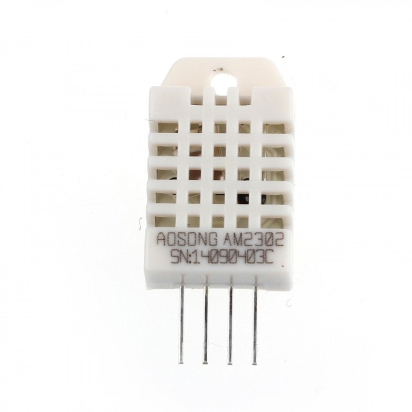
Clearing the ~29 hour memory leak induced hard limit for execution time let me run into my next failure. I was using DHT22 temperature and humidity sensors. If you don’t know what you’re doing and you’re in the Arduino world, these are ubiquitous. They’re also pretty much trash, in my experience. They work a little but there’s just no reason for them to exist when other sensors exist. The sensor can be had for ~3$ a piece, has a ±0.5°C temperature accuracy, and a 2 second sensing period. They’re not objectively terrible, and I’m sure someone more competent could make them work more reliably, but there are just so many alternatives that either have better performance, better price, better reliability, or all of the above.

dht22

My scheme was this: I didn’t want to actually go to any effort to calibrate the sensors, so if I put a bunch of them in, discarded obvious outliers and averaged the remaining values I was hoping I could get some reasonable consistency. I was reading each sensor every 2 seconds, sending the reading off to a server, then repeating. That’s when the sensor failures started to kick in…

Following another recommendation from Rob Tillaart, I tried swapping the original 10k resistors for 4.7k and started tracking specifically what the failures were. These represent the interactions with a given sensor. Here’s a snapshot:

Total			OK	Checksum error	Timeout		Unknown	
( 10k) 1: 48950		48929	21		0		0
( 10k) 2: 48950		48354	596		0		0
(4.7k) 3: 48950		46612	2336		0		0	
(4.7k) 4: 48950		47447	1503		0		0	

As you can see, it’s just shy of 50000 reads across 4 sensors – 2 with 10k resistors and 2 with 4.7k. The best sensor had a ~0.04% error rate while the worst performing sensor had a whopping 4.77% error rate! The obvious conclusion here is this is a hardware implementation/user issue and not a sensor issue, but it’s still a pain.

Ignoring the checksum errors (which just manifest as a failed read), the real issue is that 100% of the time the sensors would lock up and timeout. That is to say, at an arbitrary seeming time, every DHT22 sensor in every configuration I tried eventually locked up. I had purchased a few different form factors and manufacturers as well, so this seemed like a fundamental issue somewhere.

While I’d absolutely shattered the 28 hour continuous run record, sensors consistently started to drop off one-by-one and I couldn’t get any reading much into the second day. The program still ran fine, just not temperature or humidity data coming in. After floundering on this issue for a week or so, I ended up just cutting the power to the sensors when a timeout was detected. This gave them a chance to reboot, and seemed to work robustly enough to move forward. Again, I didn’t discover the root cause of this and enough changed over time that I’m not sure specifically what the issues were, but in my opinion in decreasing likelihood:

  • using a breadboard to hook things up (these are the cause of SO MANY of my problems)
  • using 3.3V logic – I got a logic level shifter eventually
  • timing interference from WiFi or other ESP8266 shenanigans
  • the ESP8266 itself – I got a bunch of ESP32 modules and have been using those since

Lessons learned:

  • always track your memory usage during development, memory leaks can be slow and come from unexpected places
  • just… don’t use breadboards. If anything at all is going wrong and you’re using a breadboard, assume the breadboard is the issue until proven otherwise
  • even sensors can fail! Robust software/electronics design has to accept that failure (e.g. by not burning anything down) and deal with it (e.g. by rebooting the sensor)


Convert UTC datetime to timezone in Grafana

I imagine this is one of those super common sense things that anyone who works with databases knows, but I didn’t. In my database I have a bunch of timestamps – specifically in Postgres I have columns with type timestamp with time zone. In Grafana, the time column is selected appropriately, and ends up in UTC. I couldn’t figure out a way for Grafana to convert the data (I’d love to hear it if there is). Turns out it’s trivial to edit the query to convert the timestamp. For example:

SELECT
  created_At AT TIME ZONE 'America/Toronto' AS "time",
  temperature
FROM temperature
WHERE
  $__timeFilter(client_time)
ORDER BY 1

No more mental gymnastics while looking at my dashboards! Small quality of life improvement for me, plus learned a little tiny bit.

Incubator build: Part 1 – Warm a tub

Circa early 2018, I was able to stitch together enough Arduino example code to get an ESP32 program that did the following:

  • connected to Wi-Fi
  • set the time via NTP
  • read two DHT22 temperature/humidity sensor
  • publish temperature, humidity, and time of the reading over MQTT
  • toggle a pin when heat got hotter than a threshold, and again when it got cooler than a threshold

That sounds like it’s in the realm of an incubator. It can’t adjust the humidity itself, but it can at least relay that information. By varying the size of container of water inside the incubator, an operator could theoretically get pretty close to a controlled humidity level experimentally.

This was profoundly exciting for me. I was checking off all sorts of stuff: I started completely confounded, figured out some tiny piece, and repeated:

  • I had figured out how to flash a microcontroller
  • I’d learned very high level concepts around embedded program design
  • I figured out how to get the CURRENT time on a microcontroller
    • it’s so much harder than it sounds, and it’s nothing I’ve ever had to do before
  • I’d learned about MQTT, Eclipse Mosquitto
  • some GPIO stuff was starting to make a little bit of sense, but not really
  • I was getting a very rough idea about voltage and current
    • is 50mA a lot? Of course not, that’s a tiny amount of current! Oh, from a GPIO pin? Yeah, that’s WAY too much
  • I had learned the difference between 3.3V logic and 5V logic, and practically speaking what that means
    • a common ground is obvious in retrospect, but not if you don’t know anything!
  • I’d also learned how to control a transistor to act as a digital switch

Sensing that I was close to accomplishing my dream of building an incubator, I starting the hardware build. Build 0 was a “Tuff Store” tub. It was < 5$ at Walmart, and I already had it in the house, so it fit the bill.

zoomed image

I literally dangled two DHT22 sensors off their leads and added a light bulb in a socket harvested from a broken flood light. This was attached to an ESP8266 board sitting on top, with a transistor to control a mechanical relay to turn the light bulb on and off.

20200501_125900

As you can notice, there’s no real mount for that light bulb socket. Also it looks as though there’s some discoloration on the one side of the socket. This will become relevant shortly.

As far as boxes that are warmer than room temperature goes, this one was absolutely crushing it. The occasional “tick” of the mechanical relay became reassuring background noise that everything was working as intended. Actually… that may be a bit boastful – it was alright. There were a few areas for improvement:

  • incandescent light bulbs (the ones that get hot) are hard to come by these days!
  • mounting anything to smooth plastic is tough. The options are generally drill permanent holes, use an adhesive that barely works, or use an adhesive that is permanent
  • the thin walls provided very little insulation, so heat transferred out of the box pretty readily

That said, it worked. The Arduino program was:

  • connect to Wi-Fi
  • if it had been long enough, sync the time with NTP
  • read the temperature and humidity from the DHT22
  • post temperature and humidity to an MQTT broker
  • if above a threshold temperature, turn lightbulb off. If below a threshold temperature, turn lightbulb on
  • repeat

It worked pretty much as intended. I didn’t have any way of persisting the readings, so it was hard to profile how it performed, but watching the temperature come in on an MQTT subscriber things looked pretty solid. I gradually let it sit for longer and longer. Being keenly aware of how little I know about electronics, and how shoddily my build was put together, I was cautious to not let it sit completely unattended. This ended up being prudent.

My very rudimentary Arduino program blocked while connecting to Wi-Fi. What I didn’t anticipate was that Wi-Fi wasn’t 100% guaranteed to be accessible all the time. One day, our Wi-Fi went out. The “incubator” had been in a heating state, and the program was effectively stalled because it was waiting for Wi-Fi. This meant the heater (light bulb) stayed on way longer than intended, deformed the really sub-par mount I had rested the light bulb socket on (to keep it away from the side of the container), and melted clear through the side of the plastic tub. This resulted in a bunch of burned plastic, and a light bulb shaped hole in the container.

With that, build 0 ended in catastrophic disaster. The maximum consecutive run time was around 16 hours – far short of the required 21 days. Roughly 6$ down the drain (5$ tub and 1$ light bulb). Lessons learned:

  • hobby electronics can turn into a house fire horrifyingly easily
  • even though the focus of the project was on the electronics, I couldn’t take for granted that the software would still be significant
  • “bad” decisions are okay, as long as they’re deliberate and not made recklessly
    • it’s valuable to be honest with yourself about how bad you are at things, so you can mitigate the impact of those things going horrifically wrong

Incubator build: Part 0 – Introduction

I want to build an incubator for chicken/duck/general fowl eggs. More than that, I want to actually finish the project (hatch out birds) AND I want the incubator to not suck. All 3 of these goals are particularly challenging for me, as I tend to lose interest in a project once it’s ~80% complete and never actually get to the part where it works, or it will kinda work but be fragile and miss the target. Additionally, the difference between the MVP of something and a version that is “nice” is absolutely massive. Part of that is generally re-starting some aspect, as now you actually understand the problem you’re trying to solve. The last few years are littered with the corpses of projects I have abandoned at various stages, most of them depressingly expensive (in both time and money) and depressingly incomplete.

I started trying to build an incubator over 2 years ago. The very first incubator-looking code I produced was from March of 2018. For people who know anything about electronics or hardware, that’s a bit preposterous. It’s really not that hard – incubators are pretty simple. Unless, of course, you know nothing about electronics, or soldering, or embedded development or incubating or… That’s where I started.

Through a whole bunch of trial and error, the first ever version kind of worked. I was starting with the ESP32 microcontroller. Knowing nothing about anything, I started with the Arduino wrapper for ESP32. This got me up and running pretty quickly, and there’s some kind of library for virtually every sensor you’re likely to come across. That said, the quality of some of the libraries can be pretty suspect, and the interface exposed by them often is not quite what you want. Of course, good luck determining the wheat from the chaff when you have no idea what you’re doing.

Overall, the theme of the project seems to have been: even if you’re peripherally familiar with something, having to actually implement it and make it robust from a hardware/electronics perspective means you have to actually UNDERSTAND it. Not necessarily all the way down to the physics of it, but way more intimately than what is required for web application development (which I’m familiar with). Some of the stuff I either encountered for the first time, or actually had to start trying to understand at a practical level:

  • voltage, resistance, current, power, grounding, and (much, much later on) capacitance
  • soldering, crimping, terminals, solid vs. stranded wire, wire gauge, breadboards, prototoboards
  • power supplies, stepper motors, logic level shifting, transistors, regulators, mechanical and solid state relays
  • analog sensors, digital sensors, serial communication, SPI, I²C
  • volatile vs. non-volatile memory, microcontroller power management
  • Arduino environment, ESP-IDF, cmake
  • MQTT, Eclispe Mosquitto, Postgres (TimescaleDB), Grafana, CAD, 3D printing

I fully realize people successfully hatch eggs with a cooler, an incandescent light bulb, and a container of water. As I stated at the beginning; I wanted to do this, I wanted to do it well, and I wanted to finish it. That meant a significant portion of this was straight up learning.

How to melt a stepper motor

Summary: Power a 5V stepper with 12V, and leave most of the coils energized for long periods of time

I got one of the ubiquitous packs of 5 28BYJ-48 + ULN2003 stepper driver boards. It was 18.98$ CAD in 2018 for 5 – a very reasonable price. I like cheap things like this because I don’t know anything and I’ll wreck them for sure. Also, if you can get something to work with one of these motors, then it’s easy enough to swap out for a “real” stepper after the fact, so there are few downsides.

I tried to use one of these in a project and it was my first time doing so for more than a few seconds (or just enough to prove I could turn it). I’m using an ESP32, and specifically using the Espressif IoT Development Framework (ESP-IDF) to build the software. I didn’t immediately find a stepper driver library that looked nice , and I had the step sequence on hand, so I figured I’d write my own driver. It’s nothing fancy – an array of steps, and a loop that sets the 4 pins to the corresponding value for each step in the sequence.

The included ULN2003 stepper boards show that they can take 5-12V, and as they came with a 5V stepper I assumed (I know…) the board would step the voltage down and regulate it. All it does is pass the supplied voltage on to the stepper motor though, so if you want to run a 12V stepper – you give it 12V, if you want to run a 5V stepper… you probably ought to give it 5V. In my mind, I was doing the right thing as the higher voltage would mean less current and less heat. I now realize that’s wrong for more than one reason.

As I don’t know anything, I had it do a semi-arbitrary number of steps (500), then “sleep” for a couple hours. What I didn’t pay any attention to was the coil energization between these two rotation periods. If unlucky, it could be resting with 3 out of the 4 coils energized for the entire time. The worst part is there was no reason for it – there was no load on the stepper, so it really didn’t need to hold its position.

Anyways, these look like Nylon gears to me, which means almost definitely the motor got to over 100°C (which is pretty horrifying). Now I have 4 cheap stepper motors to play with…

I didn’t even notice until I posted the pictures, but it looks like the drive gear melted completely and turned into a puddle. I assumed I had lost it while taking it apart, but obviously this motor was even worse off than I thought.

Li-Ion to 3.3 V Buck-boost Converter

Looking at powering an ESP32 from Li-lon batteries, specifically NCR18650B (3400mAh) I tried to build the circuit in Random Nerd Tutorial’s Power ESP32/ESP8266 with Solar Panels. There a MCP1700-3302E LDO regulator (PDF warning) is suggested, but when using the NodeMCU ESP-32S it could not start up Wi-Fi reliably. Every now and then it would work, but my guess is the 250mA limit was not quite enough to satisfy a current spike as the Wi-Fi turns on.

It could be that my particular board was deficient in some way, but I wanted more flexibility on the input voltage end of things anyways (e.g. boost when voltage is too low). When looking around, two chips stood out to me, the TPS63020 and TPS63060 (PDFs),

TPS63020 TPS63060
Input voltage 1.8 V – 5.5 V 2.5 V – 12 V
Output voltage 1.2 V – 5.5 V 2.5 V – 8 V
Output current @3.3 V (VIN> 2.5 V): 2A @5 V (VIN <10 V): 2 A in Buck Mode
@5 V (VIN>4 V): 1.3 A in Boost Mode
Quiescent current 25 μA < 30 μA
Operating Temperature (°C) -40 to 85 -40 to 85

They don’t seem to be sold on boards particularly commonly, so I ordered a couple of whatever I could find. I ordered two boards with the TPS63020 on them (this one, for ~13.37$ CAD, and this one, for ~7.28$ CAD) and one board with the TPS63060 on it (this one, for ~5.11$ CAD).

All of them are slightly more expensive than I was hoping, but the specs are much more in line with what I wanted compared to the LDO regulator. I’d love to find a TPS63021 (the fixed 3.3 V output chip) to play with, but no luck so far.

Visualizing 3D printer Z axis offset

This is the z-height calibration model from the Prusa forum (source below). While the number is somewhat arbitrary (as in the values will mean nothing for a different printer) it represents the distance from the PINDA probe to the print bed, where a higher number means the nozzle should be closer to the bed. These images spans from “not even making a layer” to “too close to extrude”. This is printed in ~3 year old red M3D 3D Ink PLA. I was having trouble with bed adhesion, so I figured it was worth it to go all out and give this a shot. All 4 prints are identical everything except for z-offset. Source: https://shop.prusa3d.com/forum/assembly-and-first-prints-troubleshooting-f62/life-adjust-z-my-way-t2981.html

1 - Up4V1Rh

2 - iCFrF3h

A bit of an angle shot to hopefully show off some of the texture differences. You can kind of see that at 775 it’s starting to look a bit off, and at 925 it’s similarly starting to look off.


Dell 9550 battery replacement

I was a little unhappy with how my Dell 9550 had aged. It’s 2.5 years old, but it was really seeming like it was rough. The trackpad was being finicky, it was having a hard time registering right clicks. Additionally, it was getting super hot, having trouble sleeping, and the battery life was almost nonexistent. Dell had shipped me a new battery a few months earlier, but I never got around to swapping it out.

I sat down to finally do it and looked for the instructions. Turns out the trackpad issues were exactly why Dell sent out the new battery – the battery swells up and presses on the underside of the trackpad. I opened up the back of the laptop and the heat issues immediately became clear…

20180804_124712.jpg

First impression – it’s super gross. Have you noticed the trouble spot though?

20180804_124712 - Copy.jpg

That’s where the air is supposed to go in…

computer-filth.jpg

Pulled out as much as I can get, pretty damn gross…

Turns out that dust clogging fans causes overheating issues, which cause both performance problems and does terrible things to battery life. No idea how much of the difference was from replacing the battery and how much was from unclogging the fans, but it’s night and day. I haven’t heard the fans come on since and the battery life has moved from ~45 minutes to >6 hours. Worthwhile to not be lazy. Thanks Dell, it was nice of you to send out the battery unsolicited!

UFW, OpenVPN, forwarding traffic and not breaking everything

I’ve previously written about using OpenVPN to escape Xplornet’s double NAT. Every now and then I’ll set up a new server (following the steps there) and inevitably run into some firewall configuration problem. I’ve really never taken the time to understand how to use iptables. I understand that they’re theoretically simple, but amazingly I always have a hard time with them. To that end, I’ve used ufw to try and help.

The number one piece of advice for securing anything connected to the internet is to reduce the attack surface. Great:

sudo ufw default deny incoming
sudo ufw allow ssh

and now nothing works. Attack surface minimized!

Before going to far, I use the nuclear option for new or new-ish servers to ensure I know what I’m dealing with (NOTE: this leaves your server WIDE open, don’t stop here!):

// Reset ufw and disable
sudo ufw reset

// Flush all iptables rules
sudo iptables -F
sudo iptables -X
sudo iptables -t nat -F
sudo iptables -t nat -X
sudo iptables -t mangle -F
sudo iptables -t mangle -X
sudo iptables -P INPUT ACCEPT
sudo iptables -P FORWARD ACCEPT
sudo iptables -P OUTPUT ACCEPT

This leaves me with:

$ sudo iptables -L
Chain INPUT (policy ACCEPT)
target prot opt source destination

Chain FORWARD (policy ACCEPT)
 target prot opt source destination

Chain OUTPUT (policy ACCEPT)
 target prot opt source destination
$ sudo ufw status verbose
 Status: inactive

Awesome. Clean slate! Starting from the beginning again:

$ sudo ufw default deny incoming
Default incoming policy changed to 'deny'
(be sure to update your rules accordingly)
$ sudo ufw allow ssh
Rules updated
$ sudo ufw enable
Command may disrupt existing ssh connections. Proceed with operation (y|n)? y
Firewall is active and enabled on system startup
$ sudo ufw status verbose
Status: active
Logging: on (low)
Default: deny (incoming), allow (outgoing), allow (routed)
New profiles: skip
To       Action     From
--       ------     ----
22/tcp   ALLOW IN   Anywhere

For the whole OpenVPN set up to work, the VPN client needs to actually be able to connect to the server. We’ll need to allow traffic on 1194 (or whatever port you’ve configured OpenVPN to use).

$ sudo ufw allow 1194
Rule added

You’ll also need to allow traffic to whatever port it is you’re forwarding. For example, if I want port 3000 to be what I’m exposing to the public:

$ sudo ufw allow 3000
Rule added

Leaving us with:

$ sudo ufw status verbose
Status: active
Logging: on (low)
Default: deny (incoming), allow (outgoing), allow (routed)
New profiles: skip

To       Action     From
--       ------     ----
22/tcp   ALLOW IN   Anywhere
1194     ALLOW IN   Anywhere
3000     ALLOW IN   Anywhere

That’s about it for the more intuitive parts. The server is relatively locked down, although if you are using a fixed VPN client it may be worthwhile to white-list that single address. To allow the forwarding that the OpenVPN set up relies on, we’ll need to change the ufw default forward policy. Edit /etc/default/ufw and change the value of DEFAULT_OUTPUT_POLICY from DROP to ACCEPT:

$ sudo nano /etc/default/ufw
...

# Set the default output policy to ACCEPT, DROP, or REJECT. Please note that if
# you change this you will most likely want to adjust your rules.
DEFAULT_OUTPUT_POLICY="ACCEPT"

Then disable and re-enable ufw to update it:

$ sudo ufw disable && sudo ufw enable

Finally, adding the iptables rules used in the previous post (I’m sure there’s a way to do this with ufw, I just don’t know it):

$ sudo iptables -t nat -A PREROUTING -d 183.214.158.198 -p tcp --dport 3000 -j DNAT --to-dest 10.8.0.2:3000
$ sudo iptables -t nat -A POSTROUTING -d 10.8.0.2 -p tcp --dport 3000 -j SNAT --to-source 10.8.0.1

Et voilà! A relatively locked down server that plays nicely with OpenVPN and forwarding traffic.

Replacing middle baffle support in Osburn 1600

We have an old Osburn 1600 freestanding stove (like these). Our middle baffle support rotted out. That’d be this piece in the stove (this isn’t exactly the model we have, but close enough):

StoveDiagram

Or how it looked in real life:

20161202_171451(1).jpg

It was holding the fire bricks up but it seemed like it wouldn’t be doing so for long. A couple money shots:

I contacted sbi-international.com and they helped me ensure I had the exact part number. $56.16 (after taxes) and a couple days later the piece showed up. Shockingly heavy, it’s just two pieces of steel and 6 welds. If I were more ambitious, I would have tried to weld it myself, but I already have too many projects on the go.

20171212_204614

Replacing it was actually really straightforward and easy. Nothing had to be disassembled,all the pieces are simply leaning on one another. There are 3 fire bricks on each side. There’s a bunch of space above the bricks (the smoke chamber), so pushing up the center brick is about as easy as can be. After that, the side bricks are trivial.

The remaining 5 bricks follow quickly, then the old middle baffle support basically fell out. Angle the new middle baffle support, put the bricks back in, and it’s all done.

20171214_233632.jpgTook about 15 minutes and the fireplace is good to go!