Charging Battery Modules – Part 2

The charge/discharge cycling of the modules is remarkably uneventful. Attach leads to module bolts, fasten nut on to keep it in place,  press start on the charger, wait a day and a half. Repeat, repeat, repeat…

DSC_0186.JPG

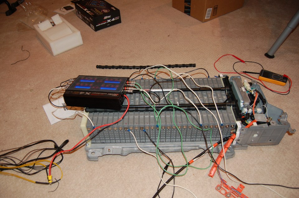
More than a little bit messy…

I tried to spread out the modules I was charging at any given time, so as to not accidentally overheat any. This ended up not being much of a concern, as almost immediately all the charge cycles became out of sync and offset themselves anyways. Having to keep an eye on all 8 was a bit of a pain – they would sometimes finish hours apart from one another.

I copied down the discharge from each of the cycles of each of the modules. Note that these follow the settings in the previous blog post (7250 mAh charge, discharge to 6V)

 Module Discharge 1 Discharge 2 Discharge 3
1 4288 5730 5874
2 4012 5608 5798
3 4067 5555 5691
4 4315 5669 5776
5 3504 5297 5583
6 4270 5730 5804
7 4414 5777 5916
8 4384 5691 5814
9 4237 5627 5697
10 4350 5659 5786
11 3256 5180 5487
12 3625 5428 5609
13 1444 1786 1811
14 3810 5571 5825
15 2346 4615 5375
16 3394 5064 5579
17 4318 5748 5885
18 3518 5475 5761
19 2190 5884 5871
20 4315 5526 5746
21 4396 5732 5858
22 4299 5635 5776
23 4372 5665 5796
24 4358 5635 5745
25 4417 5653 5758
26 4494 5668 5782
27 4095 5569 5741
28 4528 5504 5687
New module 1 3603 5319 5589
New module 2 4922 6067 6086

As you can see, it’s quite obvious that module 13 doesn’t have anywhere near the capacity of any of the other modules. This is consistent with my initial voltage check. Also, I botched the first cycle of module 15 and 19. Module 15 was still looking to be a little on the low end of the spectrum so I repeated the discharge cycle and obtained a measurement of 5579 mAh, which is much more consistent with the other modules.

As a side note, looking solely at this metric as an indicator of health, one of the new modules was the “healthiest” module I had, while the other one was almost at the bottom of the pack (but not quite). From that perspective, I’m thrilled with my purchase – it would have sucked to have gotten to this stage and only then figured out a module was garbage. Note that this doesn’t necessarily mean either of the modules is an ideal fit for my battery pack, but making that determination is beyond the means of my equipment and knowledge. My hope is that the only manifestation of the differing capacities in modules will be disproportionate wear on the “healthy” module until it’s more in line with the others.

Charging Battery Modules – Part 1

To try and get familiar with the process, I attached the battery charger to the loose modules I purchased. *This is not a good idea* – the modules can apparently expand while charging and discharging. If this were to happen to any significant degree, I imagine the modules would be unusable. As it stands, I didn’t run into any problems, but the internet tells me it’s a thing that’s possible.

DSC_0185.JPG

Things to figure out:

  • Charge rate
  • Charge cut-off capacity
  • Discharge rate
  • Discharge cut-off voltage
  • Number of cycles

To cut to the chase, this is what I settled on:

  • Somewhere around ~ 1 C charge rate, went with 5 amps
  • 7250 mAh charge
  • Somewhere around 0.1 C discharge rate, went with 0.7 amps
  • Discharge cutoff of 6V
  • 3 discharge/charge cycles

20160724_141802.jpg
This is mostly in line with, but a little different, than the main content in the PriusChat forum thread I was as using as guidance. In effect, this discharges a module at 0.7 amps until the voltage hits 6.0V. The charger cools down for a few minutes, then charges up 7250 mAh (or until it hits the , cools down for a few minutes, then repeats 2 more times. If you’d like to be mired in details and endlessly search for the “most correct” answer, this is a great spot to spin off a side project.

As a layman, this appears to be contentious amongst laymen with professionals derisively telling everyone they can’t possibly expect anything to work without equipment costing a few orders of magnitude more and a degree or two to use it properly. I found this to be a bit frustrating to research, as it seemed untenable to DIY and on a tight budget. The success of this project and others who have done the same stands as proof that sometimes the best solution is the one that’s completed. I welcome more guidance here though, I’d appreciate a concise “here’s the best way to do it”.

This whole process takes roughly a day and a half per cell +/- a few hours depending on the capacity of each module and it’s starting voltage. This is why the number of chargers is important – this isn’t going to go well if you only have one or two. With 8, depending how attentive you are, it takes a bit under a week. If you only had one (28 modules * 1.5 days/module = 42 days) I don’t think the process would go smoothly.

Lead the way

Ok, battery modules ordered, battery charger purchased, and power supplies cannibalized into an ungodly mess that would probably make an electrical engineer slap me… Next step! The considerations here are pretty simple:

  • Do they physically connect at each end?
  • Are the leads at least 20 AWG (I think I used 18 or even 16 because it’s what I had)
  • How long are the leads – this is critical when it comes to setting everything up nicely, and something I didn’t really consider and then didn’t fix…

Terminating at the charger end

We need to get all that tasty power from the charger to the battery modules. In my previous post, I suggested that I had purchased banana jacks because they sound hilarious (they sound like a cereal). That’s not the whole truth. For some reason, the battery chargers come with banana plugs as leads. I’m not exactly sure what this is designed to fit into, but I went with it. Additionally, the ports on the battery charger are banana jacks.

20160720_012649.jpg

That meant that I had to be buying banana jacks and plugs anyways, so I may as well use them for myself. I bought a package of super cheapy cheap ones:

DSC_0178

And a set of more expensive ones, that looked something like this:

31hey8cwd2l

For my purposes, they appeared identical. The difference with the “expensive ones” (I think it was ~15$ for 10, which is something like 3 times the price of the cheap ones) seems to be that they have a shroud that screws on to cover the screws that hold the wire in place. They’re also less obviously colored, because designing products with more nuanced indications of their functionality is a classic luxury goods move.

Either way, they both do the job, and they both fasten by the same mechanism:

61enmnbnt6l-_sl1000_


The shroud seemed to be a bit of a pain, as it would loosen, but the actual connection seemed to hold more sturdily on the expensive ones. And voila:

DSC_0181

Terminating at the battery module

What’s the best way to attach a lead to the battery module? Using the nuts that came off of it seems like a pretty good means. I got some appropriately sized crimp ring terminals and a crimp tool, and I was off to the races.

DSC_0164.jpg

DSC_0180

By virtue of salvaging scraps, I ended up with some stranded wire leads and some solid wire leads (can you guess which is which in the picture below?). Definitely solid wire is not the way to go for this. Fastening the connectors on both ends – crimping on one side and opposing screws on the other – was a pain. They just didn’t stay as firmly attached while I was moving them about. As you can see, I pulled apart some 16-3 wire I had lying around, so I used all 3 colors interchangeably. I relied on the colored banana plugs to keep track of things.

DSC_0179

So that part was pretty straight forward, and went about as well as could be expected. I’m really happy with the attachment to the battery module – that worked out to be virtually ideal. Low cost, easy, and about as secure as possible.

Shopping List – Power Supply

If you have a bench top power supply that can put out ~40A at 12V, awesome. I wish I had one. They appear to be super expensive when getting into that kind of current. If you don’t have one…

I really didn’t have much of an idea what I was doing when I started this. Of everything, I imagine this would be the piece that I would change the most if I were to do it again. Part of that is because I could have gotten more bang for my buck, part of that is because I imagine it was wildly unsafe the way I did it. This was all motivated by being a bit cheap, and I’m not confident this was the right place to save money. I’ve used the power supplies since though, so it’s not a write off.

What I did

Note: This PSU *had not* been used, at least since it left the factory. There are some reasonably large capacitors inside, so be careful with those. Definitely don’t plug in the power supply before disassembling, and if it is disassembled either let it sit for a day or two or manually discharge the capacitors (into something other than yourself).

Cut everything open then close it back up again

This slideshow requires JavaScript.

Group wires by voltage (color)

Figure out what the voltages are, either the easy way or the hard way. The hard way would be to strip one of each wire, figure out how to turn the PSU on, and test everything. Easy way – look up a color scheme online. Here’s a pin out for an ATX power supply, copied entirely from uzzors2k.4hv.org.

Pin

Name


Color

Description

1 3.3V


Orange +3.3 VDC
2 3.3V


Orange +3.3 VDC
3 COM


Black Ground
4 5V


Red +5 VDC
5 COM


Black Ground
6 5V


Red +5 VDC
7 COM


Black Ground
8 PWR_OK


Gray Power Ok (+5V & +3.3V is ok)
9 5VSB


Purple +5 VDC Standby Voltage (max 10mA)
10 12V


Yellow +12 VDC
11 3.3V


Orange +3.3 VDC
12 -12V


Blue -12 VDC
13 COM


Black Ground
14 PS_ON


Green Power Supply On (active low)
15 COM


Black Ground
16 COM


Black Ground
17 COM


Black Ground
18 -5V


White -5 VDC
19 5V


Red +5 VDC
20 5V


Red +5 VDC

Or summarized (not really sure where I got this from)

Black = Ground (0V)
Red = +5V, 
White = -5V terminal, 
Yellow = +12V terminal, 
Blue = -12V terminal, 
Orange = +3.3V terminal, 
Purple = +5V Standby (for standby LED and 180 to 220ohm current limit resistor)
Gray = power is on (for power LED and 180 to 220ohm current limit resistor)
Green = Turn DC on (power switch, black on ground side of SPST switch). 
Brown = senses +3.3V and should be kept connected with orange wires, 
Pink = senses +5V and should be kept with red wires.

The only tricky thing here is that power supplies can cheat a bit. For example on mine, yellow is different from yellow with a blue stripe. That tripped me up for momentarily. If you’re doing this, make sure you take a quick headcount to ensure you haven’t accidentally confounded two separate voltages.

In this instance, all I care about is the ground (black) and the +12V (yellow) – the -12V line can only put out 0.3A, so if you’ve got your leads backwards when you’re checking this it’ll become pretty obvious pretty quickly. This is one of the boneheaded mistakes that I didn’t make, but I thought about it…

Terminate them…

This is where it starts to get cringe-y. I would suggest doing a better job than I did, so you don’t burn down your house or anything. Probably it doesn’t need to be said, but I have no idea what the best practices are for something like this. Given a whole bunch of small gauge wires, how do you make one big gauge one? This worked for me – group the recommended number together into crimp terminals, then group the crimp terminals together on something else. I went with banana jacks because they sound hilarious.

So, at this stage I theoretically had 40 amps at +12VDC available. Perfect for powering the chargers! One last thing though.

Connect Green to Ground

DSC_0175

If you don’t do this, the PSU won’t put out anything at all. This is the magic “turn PSU on and solve your mysterious problem” step. If it weren’t torn open, this would likely be connected to a switch.


What I wish I had done

I think it would have been a better idea to get all the female connectors I needed, and just plug the PSU into a homemade breakout board. One step even better than that would be to realize that I’m not the first person who’s ever wanted to use an ATX power supply and do even 5 minutes of online research. I really couldn’t see the forest for the trees on this one. Products like this exist (for less than 15$): seeedstudio ATX breakout board

*sigh*

That said, most of the products I looked up after seemed to be in the same domain as bench top power supplies – the rated current is far below what I was looking for. Next time, I guess…

Shopping List – Battery Charger

The battery charger is a tough one. This seems to be a scarcely served market. You need a battery charger that can safely and effectively charge the batteries, and a power supply that can consistently power the charger. If you happen to find those two capabilities in one product, awesome! I wasn’t able to, but it seems possible that someone somewhere is making a high performance battery charger with an included power supply

I ended up turning to the RC Racing market segment for a good battery charger – I’d love to hear if there’s a better or cheaper alternative. The key at this point is parallelization. The charging process takes a long time, and acts on a single module at a time, so 28 * a long time ~= 28 long-times. Other than just being impractical, the closer this can be done to completely in unison, the easier the next steps are. To that end, as many battery chargers as possible is ideal.

One that comes recommended on PriusChat is the Hitec X4.

DSC_0183


It has a handful of convenient features, the most important for this application being an automatic charge/discharge cycle with configurable charge/discharge rates and limits. Additionally, it has 4 ports! That’s a boon for this application because it drops the price per charger significantly. Unfortunately they’re still relatively expensive, I paid $117.98 each and bought 2 units, which means 8 chargers for 30$ a piece.

As part of this project, I reached out to Hitec (super responsive!) to try and get more information about their charger. It turns out the product is just a sticker over top the SkyRC Quattro B6 80W. I reached out to SkyRC to see if I could get more information and received this pseudo-English in response:

Thank you for your inquiry.
As the charger monitor is compatible with SkyRC old items which discontinued or will discontinue, we have no plan to make update to it.
Please understand.

You can still find the Quattro for sale various places, but I don’t see an updated product on SkyRC’s website, so I can’t link that product since it’s been discontinued.

The cheaper model (the one I got) only runs off 11-15 VDC (think car battery, or perhaps more realistically a car battery charger). You *could* run it off a car battery, and if you read through the PriusChat forum there are people who did that, but it strikes me as less than ideal. I’d hate to kill the small battery by accidentally discharging it too much or something. The expensive model runs off of the mains in Canada (120 VAC), but can also run off 11 – 15 VDC. When I was buying, it was almost 100$ more expensive for the AC model, so I figured I could do DIY that part and save a little money. Here’s the AC version, looks almost identical.

I thought it’d be extra cool to collect the data while charging, so I bought the USB adapter:

Theoretically, this would allow me to talk to the charger with a computer. This turned out to barely be the case. First of all, the interface is per-charger-module. That means to collect one run off of one unit, one would need 4 adapters and perhaps more importantly, 4 USB ports connected to 4 instances of the client software. On top of this, the charger can be programmed to cycle charges and discharges. Unfortunately, it disconnects at the end of each cycle. You would have to babysit the machine the whole time if you wanted anything useful out of it. I looked at the graph from one cycle, then gave up on the unit for the rest of the project.

Shopping List – Battery Module

I mentioned earlier that I bought everything ASAP, as most of the items take a bit to ship.

The modules are pretty straightforward, as much as buying anything off of eBay ever is. I searched around for a bit, found a seller with a good reputation, and bought 2 – I only needed one, but I didn’t want to wait again if I found a second one was dead or I somehow managed to kill one.

PriusCell

They aren’t cheap at ~65$ each after exchange rate and shipping, but they’re cheaper than a new car. As I understand there’s a significant market for batteries that come from vehicles that were written off after an accident or just reached their end of life. Not a lot of people are willing to fix them, so they just get recycled or scrapped. I’m sure that will be a booming business in the next ~10 years. If you’re looking to make some money, maybe partner with a mechanic and fix hybrid/electric car batteries. There’s a small fortune to be made there, and no one remotely local who’s offering the service.


Load Testing

I have no idea how to do this. From what I read, modules that are on the threshold of being unusable can appear as though the have an appropriate voltage (as explained in the previous post), but as soon as they’re put under load (e.g. trying to drive the electric motor) the voltage drops disproportionately. So the idea is that checking the voltage of the modules gets the low hanging fruit, load testing the modules gets most of the rest of them.

Given that I have no idea how to do this, what I understood the be the process is as follows:

  1. Determine an appropriate load – one site mentioned (capacity * voltage)/5 as a good range. For an individual Prius module, that would be (6.5 Ah * 7.2 V)/5 ~= 9.4 watts. Something around there would be useful, but doesn’t need to be exact, I imagine 5 watts would do the trick as well.
  2. Check the voltage of the cell with nothing attached
  3. Apply the load
  4. Check the voltage of the cell under load

That’s about it. I skipped this step, as I had the battery chargers ready to go and figured they would be the best measure of module health. The risk, of course, being that I may waste precious time cycling modules that are no good and could have been excluded by virtue of the load test. So far as I understand it, the load test will not yield anything the discharge cycle on the battery charger wouldn’t also tell you, as that’s basically exactly what it’s doing.

Testing Battery Modules

At a high level, all a person needs to do this step is a multimeter. No one would ever confuse me with someone who knows what they’re doing with a multimeter, but for this project I think a cheap (not 5$ cheap, 30$ cheap) multimeter will do the job just fine. Without knowing anything about anything, here’s a list of the battery voltages as I initially measured them, see if you can spot the bad module(s):

Module 1 7.89
Module 2 7.88
Module 3 7.89
Module 4 7.87
Module 5 7.88
Module 6 7.88
Module 7 7.87
Module 8 7.87
Module 9 7.87
Module 10 7.86
Module 11 7.88
Module 12 7.88
Module 13 6.61
Module 14 7.87
Module 15 7.89
Module 16 7.87
Module 17 7.88
Module 18 7.88
Module 19 7.87
Module 20 7.87
Module 21 7.88
Module 22 7.88
Module 23 7.87
Module 24 7.87
Module 25 7.88
Module 26 7.88
Module 27 7.88
Module 28 7.89

To be clear, all the modules are 7.86 – 7.89v except for one. Module 13 is at 6.61 volts. Apparently it’s quite common for the center modules to go first, as they’re the most stressed by heat, being buried in the center of the pack. That is fundamentally the whole problem that this effort is trying to address, that one module is not at the same voltage as the rest. A “healthy” module would be anything over ~7.2v, although this reading is not conclusive. A module can appear healthy by this metric, but still discharge quickly or not recharge completely.

I personally have a cheap multimeter, so I retested every module twice just to be super sure, and the readings were completely consistent, so at this stage I was happy to conclude that my battery was generally fine, module 13 was toast. Not knowing anything about battery configuration, chemistries, or electronics, this is readily apparent.

The kind of cool insight comes when you learn a little bit more than the bare minimum. The Prius battery is made up of 28 modules, as measured above, and each module is made up of 6 cells. So in the same sense that the modules are hooked up to make the battery pack, the cells are hooked up to make a module. As a property of the chemistry behind a NiMH battery, the nominal cell voltage is 1.2v. 6 cells x 1.2v = 7.2v, which is what each module is rated. So looking at a healthy module, somewhere around 7.88v for me, subtracting the nominal voltage of a single cell (1.2v) yields 6.68v. Not an exact match to 6.61, but close enough that it looks like this whole debacle is because of a single dead cell in a single module in the battery pack.

THIS is the problem with Toyota’s vision for long term maintenance of their battery packs. 168 relatively cheap cells (+/- some rounding and geographic availability, but in the neighborhood of 10$ per cell, or 60$ per module is what one would pay buying in single module volumes), one of these dies and their answer is “you should probably spend a few thousand dollars, buy 168 new ones, despite the fact that 167 of your cells are still doing just fine”. This is a bit of an oversimplification, but not much.

Note that this is the nominal voltage, so exactly half way between completely charged and completely dead. The charge to voltage level is roughly linear within the operating window, with sharp spikes just outside that window. This explains why my modules are all around 7.88v – they came out of the Prius *mostly* charged.


Battery Terminal Corrosion

This was something that I was not expecting. The corrosion on the battery terminals was pretty drastic. Well, maybe not drastic, but it was visible and it didn’t look nice:

I took a handful of pictures, but it was pretty consistent over the entire battery. I had heard this was a big problem with the 1st generation batteries, to the point where some people only had to go this far to fix their “dead” battery. Clean the terminals, put them back on, keep the thousands of dollars in your pocket. My understanding was that this was addressed in the second generation batteries, but seems to still happen. Generally the negative terminal was in quite a bit worse shape than the positive, but this was all something on a side quest for me – corrosion on the contact was not what was keeping my Prius from running.

Luckily, the fix is dead easy. Add pieces to a tub, put some white vinegar in, shake it around a whole bunch. I think I also added some salt to abrade it a bit? It took a decent amount of shaking, and a couple cups of vinegar. After most of the corrosion was gone, I gave the copper plates a little scrub with sandpaper just for that beautiful coppery look.

DSC_0141

Mmm, vinegar and corroded battery terminals.

DSC_0142

Sanding things was a bit of a pain, everything was so small…

DSC_0143

Drying on the pizza box table

DSC_0144

It looks so shiny and new!


DSC_0216

Everything all clean-ish

Here’s a before/after shot to make the difference abundantly clear:

Starting the real work

CAUTION

Remember all the safety that was achieved by removing the safety plug? That starts to go out the window. All of the batteries are in series, so it’s extremely possible to complete the circuit by grabbing two contacts at the same time. On the plus side, it’ll probably be fewer of the modules so it’ll be less deadly, but still not a good time. The practice of only using one hand – touching only one “thing” at a time – is a good practice here. Until the batteries are disconnected from each other, this is dangerous.

This step is pretty straightforward, so it goes quick. Get a socket, take all the nuts off, call it a day.

Battery naked

Battery under its protective sheathing

DSC_0124

Peeling off the plastic cover that protects the bus bar

DSC_0126

Everything being shown off

DSC_0128

Close up of the plastic housing for the wiring, the bus bar, and the battery terminals

DSC_0129

The black cover shows hides how the safety plug works – it breaks the circuit instead of having the bus bar be continuous. I’m not sure why it’s close to the middle of the pack though…

DSC_0135

Take off all the nuts that hold the plate against the battery terminals

DSC_0134

About as naked as it gets!